

What Role Does the Rotor Play in Hub Motor Rotation Today?
2026-10-08
In our factory, when a Hub Motors unit arrives for repair with symptoms of jerking, reduced torque, or excessive heat, the first component we inspect is not the controller or the battery. It is the rotor. The rotor is the rotating part of the motor that carries the permanent magnets. Its alignment with the stator windings determines the timing of the electromagnetic force. Its magnetic strength determines the torque output. Its mechanical balance determines the vibration level. A rotor that is slightly misaligned or partially demagnetized can cause a cascade of problems that the controller cannot compensate for. This guide explains the rotor's function and the failure modes we see in real repairs.
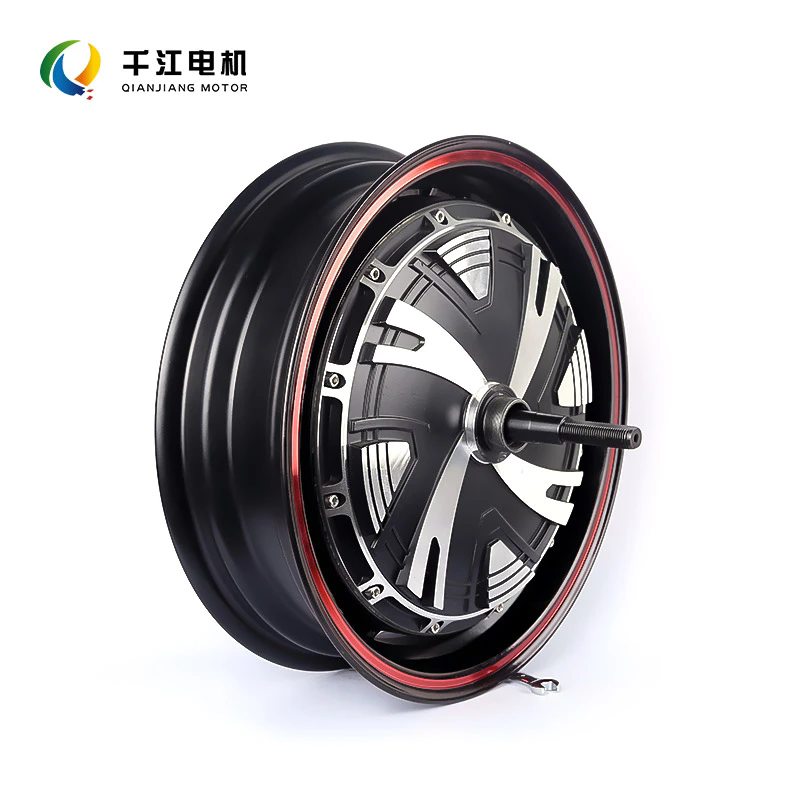
1. What Is the Rotor's Role in Generating Torque in Hub Motors?
The rotor in a Hub Motors unit carries a series of permanent magnets arranged in an alternating north-south pattern. When the controller energizes the stator coils in sequence, the magnetic field from the coils interacts with the magnetic field from the rotor magnets. This interaction produces the tangential force that rotates the rotor. The strength of the force depends on the magnetic flux density of the magnets, the current in the coils, and the alignment between the two. The table below shows the typical magnet specifications for different Hub Motors power ratings.
| Motor power rating | Magnet grade | Magnet thickness (mm) | Number of poles | Typical torque (Nm) |
| 250 W | N35 | 3.0 | 20 | 15 – 20 |
| 500 W | N38 | 3.5 | 24 | 30 – 40 |
| 750 W | N40 | 4.0 | 28 | 45 – 60 |
| 1000 W | N42 | 4.5 | 32 | 60 – 80 |
| 1500 W | N45 | 5.0 | 36 | 90 – 120 |
The magnet grade determines the flux density. A higher grade, such as N45, produces a stronger magnetic field and therefore more torque per ampere of current. In our factory, we use N38 to N45 grade magnets depending on the power rating. We also verify the magnet polarity and position after assembly to ensure that the rotor produces the correct back-EMF waveform. Ningbo Qianjiang Motor Co., Ltd. has been manufacturing Hub Motors for over 12 years and uses automated magnet placement equipment to maintain consistency.
2. How Does Rotor Magnet Alignment Affect Hall Sensor Timing?
The Hall sensors are positioned on the stator. They detect the position of the rotor magnets and send signals to the controller. The controller uses these signals to energize the correct stator coils at the correct time. If the rotor magnets are misaligned, the Hall signals will be out of phase with the actual rotor position. This causes the controller to energize the coils too early or too late, which reduces torque and increases current. The table below shows the effect of magnet misalignment on motor performance.
| Magnet misalignment | Hall signal error | Torque reduction | Current increase | Typical symptom |
| 0 – 1 degree | Negligible | < 2% | < 3% | None |
| 1 – 3 degrees | 5 – 10 degrees | 5 – 10% | 10 – 15% | Slight vibration |
| 3 – 5 degrees | 15 – 20 degrees | 15 – 25% | 25 – 40% | Jerking, noise |
| > 5 degrees | > 25 degrees | > 30% | > 50% | Motor stalls or overheats |
In our factory, we use a back-EMF test to verify the magnet alignment. The motor is spun by an external drive, and the voltage waveform is measured on each phase. A symmetric waveform indicates correct alignment. An asymmetric waveform indicates misalignment. We also check the Hall sensor output against the back-EMF waveform to ensure that the timing is correct. Ningbo Qianjiang Motor Co., Ltd. performs this test on 100 percent of our Hub Motors before shipment.
3. What Are the Common Rotor Failure Modes in Hub Motors?
In our repair workshop, we have identified four common rotor failure modes. The first is demagnetization. This occurs when the rotor is exposed to excessive temperature or a strong external magnetic field. The magnets lose their magnetic strength, which reduces torque and increases current. The second is magnet cracking. This occurs when the rotor is subjected to mechanical shock or thermal cycling. A cracked magnet can shift position or break into pieces, which causes the rotor to become unbalanced. The third is corrosion. If the rotor is not properly coated, the magnets can corrode, which weakens the magnetic field and causes debris inside the motor. The fourth is bearing wear. The rotor bearings support the rotating assembly. If they wear, the rotor can wobble, which changes the air gap and causes vibration. The table below summarizes these failure modes.
| Failure mode | Root cause | Symptom | Repair action |
| Demagnetization | Overheating (>120°C) or external field | Low torque, high current, heat | Replace rotor |
| Magnet cracking | Mechanical shock or thermal cycling | Vibration, noise, intermittent operation | Replace rotor |
| Corrosion | Moisture ingress, damaged coating | Rust debris, reduced torque | Replace rotor |
| Bearing wear | Normal wear or contamination | Radial play, vibration | Replace bearings |
In our factory, we have seen rotors that were demagnetized after only 6 months of use because the motor was overloaded on a steep hill. The controller did not have thermal protection, and the rotor temperature exceeded 150°C. The magnets lost 30 percent of their strength. The repair required a new rotor. This is why we recommend that all Hub Motors be equipped with thermal protection that reduces power when the temperature exceeds 110°C.
4. How Does Rotor Design Differ Between Direct Drive and Geared Hub Motors?
Direct drive Hub Motors have a large rotor with many poles. The rotor rotates at the same speed as the wheel. Geared Hub Motors have a smaller rotor that rotates at a higher speed, and a gear reduction system that reduces the speed to the wheel. The rotor design is different in each case. Direct drive rotors are designed for high torque at low speed. Geared rotors are designed for high speed and low torque, with the gear providing the torque multiplication. The table below compares the rotor characteristics of the two designs.
| Characteristic | Direct drive Hub Motors | Geared Hub Motors |
| Rotor diameter | Large (200 – 300 mm) | Small (80 – 120 mm) |
| Number of poles | 20 – 36 | 8 – 12 |
| Rotor speed | 200 – 400 RPM | 2,000 – 4,000 RPM |
| Magnet grade | N35 – N42 | N38 – N45 |
| Cooling | Passive (air) | Passive (air) + gear oil |
| Typical application | Cargo bikes, scooters | Commuter e-bikes |
Repair tip: When replacing a rotor in a geared Hub Motors, always check the gear assembly for wear. The gear and the rotor are matched. If the gear is worn, the new rotor will not perform correctly. In our factory, we supply rotor and gear sets as a matched pair. We also provide a shim kit to adjust the gear backlash to the correct specification.
Frequently Asked Questions About Hub Motor Rotors
Summary for Repair Technicians and OEM Engineers
The rotor is the component that converts electrical energy into mechanical torque in a Hub Motors unit. Its magnet grade, alignment, and mechanical balance determine the motor's torque, efficiency, and vibration. Rotor failures such as demagnetization, cracking, and corrosion are common in high-load or high-temperature applications. By understanding the rotor's role and the failure modes, technicians can diagnose problems more accurately and OEM engineers can specify the right rotor for the application. Ningbo Qianjiang Motor Co., Ltd. has been manufacturing Hub Motors for over 12 years and supplies to e-bike manufacturers and repair shops worldwide.
Ningbo Qianjiang Motor Co., Ltd. manufactures Hub Motors with N38 to N45 grade magnets, automated magnet placement, and dynamic balancing to ISO 1940 G6.3. We provide rotor and gear sets as matched pairs and offer a corrosion protection package for wet environments.