

How Does Custom Winding Improve Brushless Motor Performance?
2026-10-29
A drone manufacturer tests two motors on the same test stand. Both use the same stator lamination, the same magnets, and the same rotor. The first motor is wound with the standard catalog winding. At full throttle, the winding temperature reaches 105 degrees Celsius after four minutes, and the thrust begins to drop. The second motor is wound with a custom winding that has a lower phase resistance. At full throttle, the temperature stabilizes at 78 degrees Celsius, and the thrust holds for the full flight. The difference is not the iron or the magnet. It is the winding. This guide explains how custom winding improves Brushless Motor performance and what to verify when specifying it.
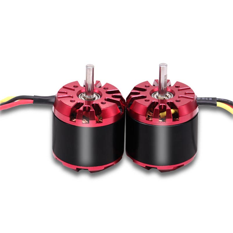
1. Why Does a Standard Winding Often Fall Short When a Brushless Motor Is Pushed to Its Limits?
A standard winding is designed for a typical load profile. The turn count, the wire diameter, and the number of parallel strands are selected to give a balanced performance across a range of applications. This balance is convenient for the catalog, but it is not optimal for any specific application. A Brushless Motor that is designed for high speed needs a low turn count and a low phase resistance to reach the target RPM without excessive back EMF. A motor that is designed for high torque needs a higher turn count to produce more torque per amp. When the standard winding is used outside its design point, the motor either cannot reach the required speed or overheats because the current is higher than necessary. In our factory, we produce Brushless Motor units with both standard and custom windings. Hongyunteng has been manufacturing brushless motors for over 10 years.
The second limitation is the slot fill. A standard winding may leave empty space in the slot. The empty space is thermal resistance. A custom winding with a higher slot fill uses the available copper more efficiently, which lowers the resistance and improves the heat path from the copper to the stator core.
2. What Does Winding Resistance Actually Do to Torque, Speed, and Heat?
The phase resistance determines the copper loss, which is the current squared multiplied by the resistance. The copper loss is the main source of heat in the motor. A lower resistance reduces the heat at the same current, or allows a higher current at the same temperature. The resistance is determined by the wire diameter, the number of parallel strands, the turn count, and the mean length per turn. The table below shows the effect of wire diameter and parallel strands on the phase resistance and the resulting performance for a 42 mm stator.
| Wire diameter and strands | Phase resistance | Continuous torque | Temperature rise at 15 A |
| 0.40 mm, 1 strand | 0.180 ohm | 0.42 Nm | 68°C |
| 0.45 mm, 1 strand | 0.142 ohm | 0.48 Nm | 56°C |
| 0.40 mm, 2 strands | 0.090 ohm | 0.55 Nm | 38°C |
| 0.45 mm, 2 strands | 0.071 ohm | 0.60 Nm | 31°C |
The table shows that doubling the number of parallel strands halves the resistance and reduces the temperature rise by more than 40 percent. The continuous torque also increases because the motor can carry more current before reaching the temperature limit. In our factory, we calculate the resistance for each winding option and verify it on a milliohm meter after winding. Hongyunteng Intelligent Technology (Xiamen) Co., Ltd. provides the resistance data with the sample motor.
3. How Does the Winding Pattern Change the Motor's Back EMF Waveform and Efficiency?
The winding pattern determines the shape of the back EMF waveform and the amount of cogging torque. A concentrated winding around each tooth produces a trapezoidal back EMF and a higher cogging torque. A distributed winding across multiple teeth produces a more sinusoidal back EMF and a lower cogging torque. The connection method, star or delta, also changes the effective parameters. The table below compares the common winding patterns and connections for a 12 slot 8 pole motor.
| Winding pattern and connection | Back EMF waveform | Cogging torque | Efficiency range |
| Concentrated, star | Trapezoidal | High | 82 – 86% |
| Concentrated, delta | Trapezoidal | High | 80 – 84% |
| Distributed, star | Sinusoidal | Low | 88 – 92% |
| Distributed, delta | Sinusoidal | Low | 85 – 89% |
Motor design engineer's note: The distributed winding with star connection gives the highest efficiency and the lowest cogging torque, but it requires a more complex winding process and a higher slot fill. The concentrated winding is simpler and cheaper, but it produces more vibration and noise. In our factory, we select the winding pattern based on the application. For a drone propeller, the low cogging torque of the distributed winding is important for smooth video. For a power tool, the higher torque density of the concentrated winding is more important. Hongyunteng Intelligent Technology (Xiamen) Co., Ltd. provides both patterns and can advise on the best choice.
4. Why Does Custom Winding Need to Be Verified Against the Actual Load Profile?
A custom winding is designed for a specific load profile. The load profile has three key points: the starting torque, the continuous operating point, and the peak speed. The winding must produce enough torque at the starting point without exceeding the current limit of the driver. It must operate at the continuous point without exceeding the temperature limit of the insulation. It must reach the peak speed without excessive back EMF that would limit the current. The verification is done on a dynamometer with the actual driver and the actual load. In our factory, we wind a sample motor with the proposed winding and test it on the dynamometer at the three key points. We measure the torque, the speed, the current, and the temperature. Hongyunteng Intelligent Technology (Xiamen) Co., Ltd. provides the test report with the sample motor.
We also check the insulation class. A winding that operates at a higher temperature requires a higher insulation class, such as class F or class H. The insulation class determines the maximum allowable temperature and the service life. A class B winding that operates at 105 degrees Celsius will have a shorter life than a class F winding that operates at the same temperature.
5. How Should Designers Specify and Verify a Custom Winding for a Brushless Motor?
The specification should include six items. The first is the rated voltage and the driver current limit. The second is the number of pole pairs. The third is the target speed and torque at the continuous point. The fourth is the peak speed and the peak torque. The fifth is the slot fill limit and the wire diameter. The sixth is the insulation class and the connection method. The verification should include four tests. The first is the phase resistance test. The second is the back EMF constant test. The third is the blocked torque test. The fourth is the temperature rise test at the continuous point. In our factory, we perform these tests on every custom winding sample and provide the test report with the shipment. Hongyunteng Intelligent Technology (Xiamen) Co., Ltd. also offers a design review to check the winding against the driver and the load before the sample is built.
We recommend that the designer provide the full load curve, not just a single operating point. A winding that is optimized for one point may perform poorly at another point. The load curve allows the designer to check the torque margin across the full speed range and to avoid a winding that is too aggressive at the high speed end or too weak at the low speed end.
Frequently Asked Questions About Custom Winding for Brushless Motors
Summary for Motor Designers and Application Engineers
Custom winding improves Brushless Motor performance by matching the phase resistance, the slot fill, the winding pattern, and the connection method to the actual load profile. A lower resistance reduces the copper loss and the temperature rise, which allows a higher continuous torque. A distributed winding with a star connection produces a sinusoidal back EMF and a lower cogging torque. The custom winding must be verified on a dynamometer at the starting, continuous, and peak operating points, and the insulation class must be checked against the operating temperature. Hongyunteng Intelligent Technology (Xiamen) Co., Ltd. has been manufacturing brushless motors for over 10 years and provides full custom winding design and verification support for our customers.