

Article Summary: Hydraulic motors convert pressurized hydraulic fluid into mechanical rotation, helping industrial and mobile equipment deliver the torque and speed required for demanding operations. Choosing the right HMK Series Hydraulic Motor involves more than comparing dimensions or purchase prices. Buyers need to understand torque, displacement, operating pressure, flow rate, speed range, installation requirements, and service conditions. This guide explains hydraulic motor operation, practical selection methods, common performance problems, maintenance practices, and application considerations. It also outlines how working with Ningbo Helm Tower Hydraulic Co., Ltd. can support a more informed hydraulic motor purchasing decision.
Who is this guide for? Equipment manufacturers, hydraulic system designers, distributors, maintenance engineers, procurement managers, and industrial operators looking for dependable hydraulic drive solutions.
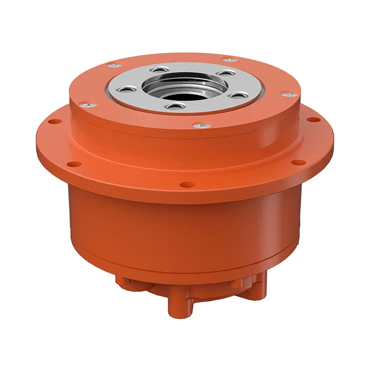
1. Understanding the HMK Series Hydraulic Motor
Hydraulic motors play a central role in equipment that requires controlled rotary motion, high torque, or reliable operation under changing loads. They are commonly found in machinery where electric drives may not provide the most practical combination of power density, layout flexibility, and integration with existing hydraulic systems.
The HMK Series Hydraulic Motor is a product designation that buyers can use to identify the relevant motor family when discussing equipment requirements with a supplier. Before purchasing, it is important to confirm the exact model, internal design, rated operating conditions, mounting dimensions, and shaft configuration from the manufacturer's technical documentation. Specifications should never be assumed to be identical across all models carrying a similar series name.
For machinery manufacturers, an appropriate motor helps balance torque delivery, rotational speed, energy consumption, and equipment size. For maintenance teams, a correctly matched replacement can reduce installation complications and help restore equipment performance without unnecessary changes to the hydraulic circuit.
Torque for Demanding Loads
Hydraulic motors can provide substantial rotational force in a compact package when the pressure, displacement, and mechanical design are appropriately matched.
Flexible System Integration
Motor selection can be coordinated with pumps, valves, hoses, controls, and mechanical transmission components to meet application requirements.
Controllable Rotation
Adjusting hydraulic flow can regulate motor speed within the manufacturer's permitted operating range.
Practical Replacement Planning
Verifying the original motor's model and interface details helps avoid fitment problems during repairs and equipment upgrades.
2. How a Hydraulic Motor Works
A hydraulic motor converts hydraulic energy into mechanical energy. Pressurized fluid enters the motor and acts on internal components designed to create rotational movement. The motor shaft then transfers this movement to the driven equipment, such as a conveyor, winch, wheel drive, mixer, or other rotating mechanism.
Step 1: The Hydraulic Pump Supplies Fluid
A hydraulic pump draws fluid from a reservoir and supplies it to the circuit. The pump establishes the flow needed for motor rotation, while the load and system resistance influence the pressure required to produce the desired torque. The pump, valves, and motor must be selected as a coordinated system.
Step 2: Pressurized Fluid Enters the Motor
Hydraulic fluid enters the motor through the designated inlet passage. Depending on the motor's internal design, pressure acts on rotating or reciprocating elements that generate torque. Port connections and the approved direction of rotation must be confirmed against the relevant model documentation.
Step 3: Internal Components Generate Rotation
The motor's displacement determines how much fluid is theoretically required for each revolution. For a given flow rate, a smaller displacement generally produces a higher rotational speed, while a larger displacement generally provides greater torque at the same pressure differential. Actual output is affected by volumetric and mechanical losses.
Step 4: The Output Shaft Drives the Load
Rotation passes through the output shaft to the connected equipment. Couplings, keys, splines, bearings, and mounting structures must be suitable for the transmitted torque and the loads created by the driven mechanism. Excessive shaft side loading or misalignment can shorten service life.
Step 5: Fluid Returns to the Circuit
After transferring energy, the fluid leaves through the designated outlet and returns to the system or continues through the circuit, depending on the configuration. Return-line resistance, oil temperature, filtration, and any required case-drain connection can influence motor reliability.
3. Key Performance Benefits of a Properly Selected Hydraulic Motor
High Torque in a Compact Drive System
Hydraulic motors are valuable in applications where significant torque must be delivered within limited installation space. A suitable motor can drive heavy loads without requiring an oversized mechanical drive arrangement. However, achievable torque depends on displacement, pressure differential, efficiency, and the motor's rated operating limits.
Adaptability to Variable Operating Conditions
Many hydraulic systems operate under changing loads. With suitable pumps, flow controls, valves, and pressure regulation, the motor can support the speed and force requirements of different operating stages. The control circuit must be designed to prevent excessive pressure, overheating, and unstable movement.
Integration with Existing Hydraulic Equipment
For OEMs and replacement buyers, using a motor compatible with the existing circuit can simplify engineering work. Confirming port size, shaft geometry, mounting dimensions, rotation requirements, and fluid compatibility before ordering reduces the likelihood of costly modifications.
Potential for Reliable Long-Term Operation
Hydraulic motor reliability depends on the quality of the component, correct application, clean fluid, proper installation, and appropriate maintenance. A well-matched motor operating within its specified limits can help reduce unexpected interruptions and support predictable equipment servicing.
Flexible Drive Arrangement
Hydraulic motors can be installed in different machine layouts and connected to gearboxes, wheels, drums, rollers, or other mechanical components. This flexibility can be especially useful when designing equipment with space restrictions or specialized movement requirements.
4. Industrial and Mobile Applications
The appropriate application for an HMK Series Hydraulic Motor depends on its verified technical specifications and the needs of the complete machine. Hydraulic motors are widely used in the following types of equipment when the motor's torque, speed, pressure, and mounting characteristics are suitable.
Construction Machinery
Construction equipment may use hydraulic motors for selected rotary drives, winches, attachments, and auxiliary mechanisms. These applications often involve changing loads, vibration, and challenging environments. Buyers should confirm the motor's operating duty, pressure limits, shaft loading, and protection requirements.
Agricultural Equipment
Agricultural machinery can require hydraulic rotation for material handling, feed systems, selected harvesting mechanisms, and auxiliary drives. Dust, moisture, temperature variation, and intermittent operation should be considered when specifying the motor and its sealing arrangements.
Material Handling and Conveying
Hydraulic motors can power conveyor drives, rollers, drums, and other material handling mechanisms. The design must account for starting torque, loaded starts, speed regulation, and stopping behavior. A motor should not be selected using continuous operating torque alone if the application has high breakaway loads.
Industrial Processing Machinery
Mixing equipment, rotating platforms, specialized production machines, and selected processing systems may use hydraulic drives when variable torque and compact installation are useful. Engineers should also assess heat generation, duty cycle, noise requirements, and the consequences of an unexpected stoppage.
Marine and Specialized Equipment
Some marine and specialized machines use hydraulic motors for auxiliary functions or controlled rotary movement. Corrosion protection, environmental exposure, fluid temperature, installation orientation, and applicable industry requirements must be evaluated before selecting a motor for these conditions.
5. How to Select the Right HMK Series Hydraulic Motor
Choosing the right hydraulic motor starts with understanding the load and the operating conditions. Selecting by product name or physical size alone can lead to insufficient torque, excessive speed, overheating, mounting difficulties, or premature failure.
Step 1: Calculate the Required Output Torque
Determine the torque needed to start and operate the driven equipment. Include friction, acceleration, transmission losses, load variation, and any peak demand. If a gearbox or other transmission is installed between the motor and the load, account for its ratio and efficiency.
Step 2: Determine the Required Speed
Identify the normal operating speed and the acceptable minimum and maximum speeds. For a given motor displacement, theoretical speed is proportional to fluid flow. Actual speed also depends on volumetric efficiency, leakage, load, and the operating conditions of the hydraulic circuit.
Step 3: Confirm Available Pressure and Flow
Check the pump's actual flow delivery and the pressure differential available across the motor under load. Include the pressure losses in valves, hoses, fittings, and other components. The selected motor must operate within its approved pressure and flow limits throughout the intended duty cycle.
Step 4: Match the Mechanical Interface
Verify mounting flange dimensions, shaft diameter, shaft type, key or spline configuration, port arrangement, and available installation space. If replacing an existing motor, use the nameplate and original drawings wherever possible rather than relying on visual similarity.
Step 5: Evaluate Duty Cycle and Environment
Identify whether the motor will operate continuously, intermittently, or under repeated starts and stops. Record ambient temperature, hydraulic oil temperature, dust, moisture, vibration, and other environmental conditions that may influence sealing, lubrication, and heat dissipation.
Step 6: Verify the Complete System
Review the pump, relief valve, directional control valve, return circuit, filtration, reservoir, cooling arrangement, and any required case drain. A motor may be correctly sized in isolation but perform poorly when installed in a circuit that cannot maintain adequate flow, pressure, or fluid condition.
| Selection Factor | Information to Confirm | Why It Matters |
|---|---|---|
| Torque | Continuous, starting, and peak load requirements. | Prevents stalling and inadequate load capacity. |
| Speed | Normal speed and permitted operating range. | Ensures the machine achieves its required operating rate. |
| Displacement | Model-specific displacement per revolution. | Links required flow with speed and torque characteristics. |
| Pressure | Operating and peak differential pressure. | Helps avoid overload and pressure-related damage. |
| Flow | Available pump flow under actual conditions. | Determines whether the target motor speed can be achieved. |
| Mounting | Flange, shaft, ports, and installation dimensions. | Reduces replacement and assembly problems. |
| Operating environment | Temperature, contamination, moisture, and duty cycle. | Influences reliability, sealing, and maintenance needs. |
6. Understanding Important Technical Specifications
Reading a hydraulic motor datasheet correctly helps buyers compare models and communicate more clearly with suppliers. The following specifications are especially important when assessing an HMK Series Hydraulic Motor.
Displacement
Displacement is typically expressed in cubic centimeters per revolution (cm³/rev). It describes the theoretical volume of fluid associated with one revolution. Larger displacement generally produces more theoretical torque for the same pressure differential, but it also requires more flow to achieve the same speed.
Operating Pressure
Pressure ratings may distinguish between continuous, intermittent, and peak operating conditions. These values are not interchangeable. The maximum permitted pressure and the duration of any intermittent or peak condition must be confirmed from the model-specific documentation.
Flow Rate and Rotational Speed
Flow rate is commonly measured in liters per minute (L/min), while speed is measured in revolutions per minute (rpm). The required flow depends on displacement and volumetric efficiency. Operating the motor beyond its approved speed range can increase wear and heat generation.
Torque and Power
Torque describes the motor's rotational force, while mechanical output power reflects both torque and speed. Actual output is lower than the theoretical value because of internal hydraulic and mechanical losses. Datasheet ratings should be interpreted alongside the specified operating conditions.
Fluid Compatibility and Temperature
Hydraulic fluid must meet the manufacturer's requirements for viscosity, lubricity, material compatibility, and temperature range. Fluid that is too viscous can increase resistance during cold starts, while fluid that is too thin may increase leakage and reduce lubrication under hot operating conditions.
7. Factors Affecting Hydraulic Motor Performance and Efficiency
Hydraulic Fluid Cleanliness
Contaminated oil can damage precision surfaces, accelerate wear, obstruct control components, and contribute to internal leakage. Use filtration suitable for the hydraulic system and follow the specified cleanliness requirements. New oil should not automatically be assumed to be clean enough for direct use.
Operating Temperature
Excessive temperature can reduce fluid viscosity, accelerate oil degradation, and affect seals. Heat may result from prolonged overload, excessive throttling, unsuitable flow settings, restricted return lines, or inadequate cooling. Temperature should be evaluated as part of the whole hydraulic system.
Pressure and Load Matching
Repeated operation at excessive pressure can shorten motor life. A motor that is too small for the load may struggle to start or maintain speed, while an oversized motor may require more flow than the available pump can supply. Correct sizing helps avoid these problems.
Return-Line Resistance
Restricted return passages, undersized hoses, blocked filters, and unsuitable fittings can raise return pressure. Depending on the motor design, excessive return or case pressure can cause leakage, seal failure, or internal damage. Observe all model-specific return and case-drain requirements.
Mechanical Alignment
Poor coupling alignment, excessive radial loads, axial loads beyond the permitted limit, or an unsuitable mounting structure can increase bearing stress. Check the mechanical drive arrangement during installation and after any major equipment repair.
Control Circuit Design
Sudden load changes and abrupt valve operation can create pressure spikes or uncontrolled movement. Appropriate pressure relief, flow regulation, and load-control measures should be selected according to the application, especially when the driven equipment has high inertia or must stop safely under load.
8. Maintenance and Troubleshooting
Preventive maintenance helps identify developing hydraulic problems before they lead to equipment failure. The correct inspection interval depends on operating hours, load severity, fluid conditions, environmental exposure, and the manufacturer's instructions.
Recommended Maintenance Checklist
- Check hydraulic fluid level, appearance, and condition according to the service plan.
- Inspect hoses, fittings, ports, and seals for leaks or visible damage.
- Monitor operating pressure, flow, speed, and oil temperature for unusual changes.
- Inspect couplings, mounting bolts, and connected mechanical components.
- Replace or service filters according to the specified maintenance interval and condition indicators.
- Check the return circuit and any required case-drain line for restrictions.
- Record operating symptoms, maintenance actions, and replacement part details.
Common Problems and Possible Causes
| Symptom | Possible Cause | Recommended Check |
|---|---|---|
| Motor fails to rotate | Insufficient flow, incorrect valve position, excessive load, or mechanical seizure. | Verify circuit operation, available flow, pressure, and mechanical freedom. |
| Low rotational speed | Insufficient pump flow, internal leakage, or excessive load. | Measure flow and pressure under operating conditions and inspect the circuit. |
| Insufficient torque | Low pressure differential, overload, or excessive internal leakage. | Check pressure across the motor and compare load requirements with motor ratings. |
| Excessive oil temperature | Continuous overload, excessive throttling, restricted return, or cooling problems. | Inspect system pressure losses, cooler performance, and operating duty. |
| Abnormal noise or vibration | Air in the system, cavitation, misalignment, or mechanical wear. | Check fluid supply, inlet restrictions, coupling alignment, and mounting condition. |
| External oil leakage | Damaged seals, loose connections, or excessive pressure. | Identify the leak source and verify the relevant pressure and sealing conditions. |
Before inspection or repair, shut down the machine, isolate energy sources, and release stored hydraulic pressure according to the equipment manufacturer's procedures. Hydraulic fluid under pressure can penetrate skin and cause severe injury. Never use a hand to search for a pressurized leak. Suspected injection injuries require immediate emergency medical treatment.
9. Installation Best Practices for Long-Term Reliability
Correct installation protects the motor and helps the hydraulic system achieve its intended performance. Even a suitable motor may experience premature failure if the hydraulic circuit, mounting arrangement, or fluid supply is incorrect.
Verify the Model Before Assembly
Check the model code, mounting dimensions, shaft configuration, port identification, and rotation requirements. Compare these details with the equipment drawings and the supplier's technical documentation before connecting the motor.
Prepare the Hydraulic Circuit
Ensure that the system has suitable filtration, clean fluid, correctly sized hoses, and appropriate pressure protection. Flush contaminated or newly modified circuits according to the applicable cleaning procedure before connecting sensitive hydraulic components.
Align the Mechanical Drive
Make sure the motor mounting surface is stable and the coupling is aligned within the specified tolerance. Avoid using the motor shaft to compensate for misaligned machinery. Confirm that the driven load does not impose unacceptable radial or axial forces.
Follow the Commissioning Procedure
Prime or fill the motor as required by the manufacturer, verify any case-drain connections, and follow the approved startup procedure. Begin at a suitable low-risk operating condition and check for leaks, abnormal sound, temperature changes, and unexpected movement before moving to normal production.
Keep Accurate Service Records
Document the installation date, model identification, fluid type, operating readings, and maintenance history. These records make future troubleshooting easier and help maintenance teams recognize gradual changes before a serious failure occurs.
10. Working with Ningbo Helm Tower Hydraulic Co., Ltd.
Choosing a hydraulic motor supplier involves more than obtaining a price quotation. Buyers also need accurate model identification, reliable technical information, compatible installation dimensions, and a clear understanding of the motor's permitted operating conditions.
Ningbo Helm Tower Hydraulic Co., Ltd. is the company name to reference when making inquiries about the HMK Series Hydraulic Motor. When discussing your requirements with the company, provide the intended application and the available hydraulic system data so the appropriate product specifications can be verified.
Information to Prepare for Your Inquiry
- Application: Describe the machine and the function performed by the motor.
- Existing model: Provide the current motor model code, nameplate information, or technical drawing when available.
- Operating requirements: Specify target speed, continuous and peak torque, pressure, and available flow.
- Installation details: Share mounting dimensions, shaft configuration, port arrangement, and connection requirements.
- Working conditions: Explain the operating duty, oil temperature, ambient environment, and expected load changes.
- Purchasing needs: Clarify required quantities, delivery expectations, and any documentation needed for your project.
Before confirming an order, request the applicable datasheet and verify displacement, rated pressure, speed range, torque characteristics, allowable temperature, fluid requirements, and mechanical interface dimensions. Confirm any application-specific limits directly with the supplier rather than relying on assumptions based on the series name alone.
For equipment manufacturers, distributors, and maintenance teams, this preparation can make product evaluation more efficient and reduce the risk of selecting a motor that does not match the intended system.
11. Frequently Asked Questions
1. What is an HMK Series Hydraulic Motor?
HMK Series Hydraulic Motor is a product designation used to identify a hydraulic motor family. The exact design, displacement, pressure ratings, speed range, and mounting specifications should be confirmed from the documentation for the particular model.
2. How does an HMK Series Hydraulic Motor generate torque?
Pressurized hydraulic fluid acts on the motor's internal components to create rotational force. Available torque depends primarily on the pressure differential and displacement, with actual output affected by mechanical efficiency and operating conditions.
3. How do I calculate the required hydraulic motor flow?
For preliminary sizing, theoretical flow in liters per minute can be estimated by multiplying displacement in cubic centimeters per revolution by rotational speed in revolutions per minute and dividing by 1,000. The required supply flow must then account for volumetric efficiency and actual operating conditions.
4. What determines the torque of a hydraulic motor?
The main factors are displacement and the pressure difference between the motor inlet and outlet. Actual torque is lower than theoretical torque because of mechanical losses. The motor must remain within its rated pressure and torque limits.
5. Can I replace an existing hydraulic motor with an HMK series model?
A replacement may be possible if the model meets the application's hydraulic and mechanical requirements. Verify mounting dimensions, shaft geometry, port configuration, displacement, pressure, speed, rotation, and any case-drain requirements before installation.
6. Why does a hydraulic motor lose speed under load?
Possible causes include insufficient pump flow, excessive load, internal leakage, restricted lines, or a control valve problem. Measure actual flow and pressure under operating conditions to help identify the cause.
7. Which hydraulic oil should I use?
Use a fluid that meets the manufacturer's viscosity, lubrication, material compatibility, and temperature requirements. Check the specific model documentation and the requirements of the complete hydraulic system before choosing or changing fluid.
8. How can I extend hydraulic motor service life?
Maintain fluid cleanliness, use the correct oil, prevent overload, monitor operating temperature, ensure suitable return and case-drain conditions, and inspect mechanical alignment. Regular maintenance helps identify problems before they lead to major component damage.
9. What causes a hydraulic motor to overheat?
Common causes include continuous overload, excessive pressure losses, restricted return flow, internal leakage, unsuitable fluid viscosity, and inadequate cooling. Diagnose the complete circuit rather than assuming the motor alone is responsible.
10. What information should I provide when requesting a quotation?
Provide the model code if known, application, required torque and speed, available pressure and flow, mounting details, operating conditions, quantity, and any project-specific requirements. This information helps the supplier assess compatibility and provide relevant technical documentation.
Conclusion: Make Hydraulic Motor Selection a Performance Decision
An HMK Series Hydraulic Motor should be selected according to the actual demands of the machine, not simply its name or dimensions. Torque, speed, displacement, pressure, flow, fluid conditions, mounting compatibility, and operating duty all influence whether a motor can deliver dependable performance.
By confirming technical specifications before purchase, designing a compatible hydraulic circuit, following correct installation procedures, and maintaining clean hydraulic fluid, equipment owners can reduce avoidable downtime and improve the reliability of their drive systems.
For buyers evaluating an HMK Series Hydraulic Motor, careful preparation and clear technical communication with Ningbo Helm Tower Hydraulic Co., Ltd. can help make the selection and purchasing process more straightforward.
Looking for an HMK Series Hydraulic Motor?
Choosing the right hydraulic motor starts with understanding your machine's torque, speed, pressure, flow, and installation requirements. Prepare your application details and verify the specifications needed for a compatible hydraulic drive solution.
Whether you are sourcing motors for new equipment, planning a replacement, or evaluating options for an industrial project, contact us to discuss your requirements and request further product information from Ningbo Helm Tower Hydraulic Co., Ltd.