

How Does an Integrated Outer-Rotor Structure Work in Hub Motors?
2026-10-10
A chassis engineer is evaluating two Hub Motors for an electric scooter. Motor A is an inner-rotor design with a gear reduction. Motor B is an integrated outer-rotor design with direct drive. Motor B is 3 kg heavier at the wheel. The engineer expects the heavier motor to degrade handling. Instead, the test riders report that Motor B feels more stable in corners and has better traction on wet pavement. The engineer investigates and finds that the outer-rotor design produces a higher torque at low speed and a smoother torque delivery. The additional unsprung mass is offset by the elimination of the gear reduction and the improved torque response. This guide explains how the integrated outer-rotor structure works and why it changes the vehicle dynamics.
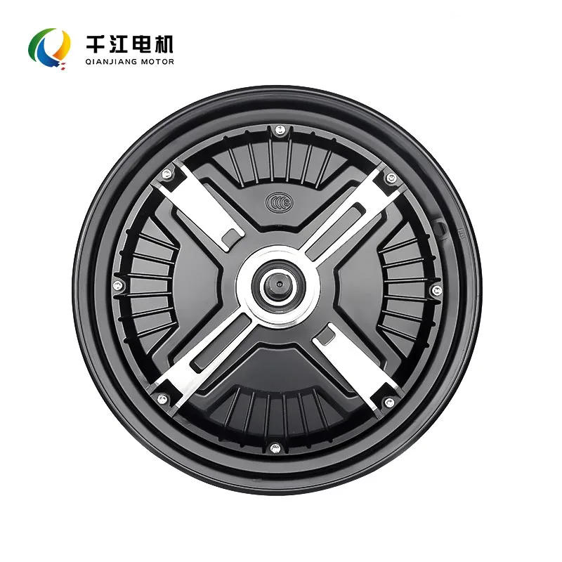
1. What Is the Structural Difference Between Inner-Rotor and Outer-Rotor Hub Motors?
In an inner-rotor Hub Motors, the permanent magnets are mounted on the rotor, which is inside the stator. The stator windings are on the outside. The rotor spins inside the stator. The torque is transmitted through a gear reduction to the wheel. In an outer-rotor design, the magnets are mounted on the outer shell, which is part of the wheel. The stator is inside. The outer shell rotates around the stator. The torque is transmitted directly to the wheel without a gear reduction. The table below compares the structural features of the two designs.
| Feature | Inner-rotor with gear reduction | Integrated outer-rotor (direct drive) |
| Magnet location | Inner rotor | Outer shell |
| Stator location | Outer | Inner |
| Torque transmission | Through gear reduction | Direct to wheel |
| Number of moving parts | Higher (gears, bearings) | Lower (rotor, bearings) |
| Axial width | Wider (gear box) | Narrower (integrated) |
The integrated outer-rotor structure eliminates the gear reduction, which reduces the number of moving parts and the axial width. The direct drive also eliminates the gear whine and the backlash that can occur in geared hub motors. In our factory, we manufacture Hub Motors with both inner-rotor and outer-rotor configurations. Ningbo Qianjiang Motor Co., Ltd. has been producing hub motors for over 12 years.
2. How Does the Outer-Rotor Structure Generate Torque at Low Speed?
The torque of a hub motor is proportional to the product of the magnetic flux, the current, and the number of turns. In an outer-rotor design, the magnets are on a larger diameter than in an inner-rotor design. The larger diameter increases the magnetic flux and the torque arm. This means that for the same current, the outer-rotor motor produces more torque. The table below compares the torque output of an inner-rotor and an outer-rotor motor with the same stator diameter and the same current.
| Parameter | Inner-rotor (with 4:1 gear) | Outer-rotor (direct drive) |
| Motor torque (Nm) | 12 | 18 |
| Wheel torque after gear (Nm) | 48 | 18 |
| Wheel speed at 3,000 RPM motor | 750 RPM | 3,000 RPM |
| Vehicle speed at 10 inch wheel | 10 km/h | 40 km/h |
| Efficiency at low speed | 75% (gear losses) | 88% (no gear losses) |
The inner-rotor motor with a 4:1 gear produces 48 Nm at the wheel, which is higher than the 18 Nm of the outer-rotor motor. But the outer-rotor motor produces its torque at a higher speed, which means the vehicle can travel faster for the same motor RPM. The efficiency at low speed is also higher because there are no gear losses. In our factory, we design the outer-rotor motor to produce a flat torque curve from 0 to 1,500 RPM, which provides good acceleration and hill climbing. Ningbo Qianjiang Motor Co., Ltd. provides torque-speed curves for all of our hub motors.
3. How Does the Integrated Structure Affect Thermal Management?
The integrated outer-rotor structure affects thermal management in two ways. First, the outer shell is part of the wheel, so it is exposed to the airflow. This helps to dissipate the heat generated by the stator windings. Second, the stator is inside the rotor, so the heat must pass through the air gap and the rotor before it reaches the outside. This is a disadvantage because the air gap is a poor conductor of heat. The table below compares the thermal performance of the two designs.
| Thermal parameter | Inner-rotor with gear | Integrated outer-rotor |
| Heat source | Stator + gearbox | Stator only |
| Heat path to ambient | Through housing and gearbox oil | Through air gap, rotor, and shell |
| Thermal resistance | 0.8 K/W | 1.2 K/W |
| Continuous power rating | 500 W | 400 W |
| Peak power duration | 60 seconds | 45 seconds |
The thermal resistance of the outer-rotor design is higher because of the air gap. This limits the continuous power rating. To compensate, we use a thermally conductive potting compound to fill the gap between the stator and the housing. This reduces the thermal resistance to 0.9 K/W and increases the continuous power rating to 480 W. In our factory, we also use a stator with a high thermal conductivity insulation class (Class H) to withstand the higher temperatures. Ningbo Qianjiang Motor Co., Ltd. tests the thermal performance of every hub motor design on a dynamometer with a controlled ambient temperature.
4. How Does Unsprung Mass Affect Vehicle Dynamics?
The unsprung mass is the mass of the components that are not supported by the suspension, including the wheels, tires, brakes, and hub motors. An increase in unsprung mass reduces the ability of the suspension to keep the tire in contact with the road. This can cause a loss of traction on bumpy surfaces and a deterioration in ride comfort. The table below shows the effect of unsprung mass on vehicle dynamics.
| Unsprung mass increase | Effect on ride comfort | Effect on traction | Effect on cornering |
| +1 kg | Slight deterioration | Negligible | Negligible |
| +3 kg | Moderate deterioration | Slight loss on rough roads | Stable (more inertia) |
| +5 kg | Significant deterioration | Noticeable loss | Slower turn-in |
| +8 kg | Severe deterioration | Poor traction | Unstable |
Chassis engineer's note: The effect of unsprung mass depends on the suspension design. A well-tuned suspension with a high spring rate and a good damping curve can compensate for an additional 3 to 5 kg of unsprung mass. In our factory, we work with vehicle manufacturers to tune the suspension for the specific hub motor weight. We also recommend using a lighter wheel rim and tire to offset the motor weight. For a 10-inch wheel, a forged aluminum rim saves 0.8 kg compared to a cast rim.
Frequently Asked Questions About Integrated Outer-Rotor Hub Motors
Summary for Chassis Engineers
The integrated outer-rotor structure in Hub Motors provides direct drive, higher low-speed torque, and fewer moving parts. It also increases unsprung mass and thermal resistance. The trade-offs must be managed through careful design of the suspension, the thermal path, and the rotor material. For electric two-wheelers, the outer-rotor hub motor is a good choice for city commuting and light off-road use. Ningbo Qianjiang Motor Co., Ltd. has been manufacturing Hub Motors for over 12 years and provides full engineering support for vehicle integration.
Ningbo Qianjiang Motor Co., Ltd. manufactures Hub Motors with integrated outer-rotor structures, direct-drive configurations, and thermally conductive potting. We provide torque-speed curves, thermal test reports, and vehicle integration support for all of our products.